Sunday, November 27, 2011

Pump Duse or Unit Injector system

This is one step higher than the Common Rail system which is found in current generation of diesel engines and this technology is also called as the Unit Injector system. This kind of engines are normally found in VW Group engines which are tagged under the name of TDi.


Construction:

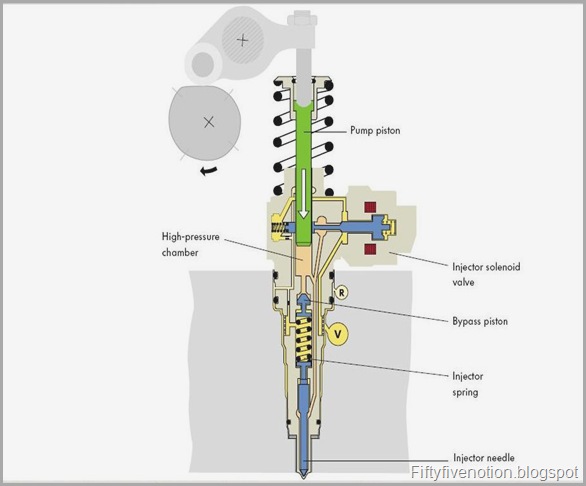
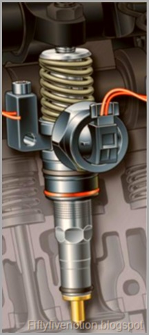
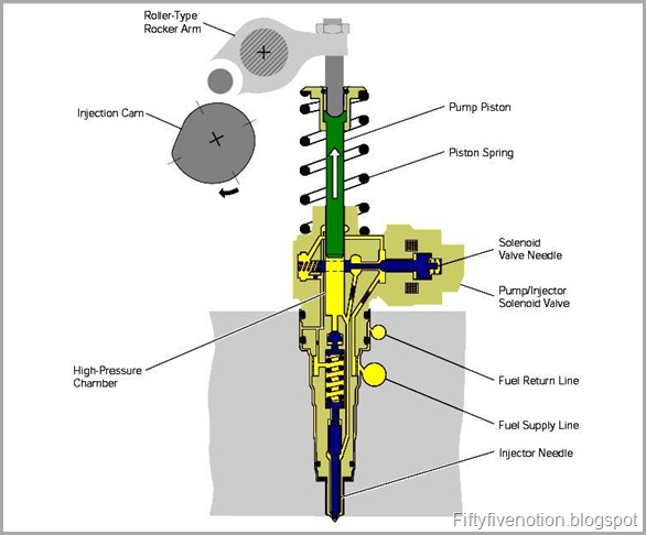
In simple the common rail system have one high pressure pump in common to all the cylinders whereas in the PD or unit injector system each cylinders will have an high pressure pump which is cam operated thus pressurizes the fuel and send’s them to the combustion chamber. The Injectors are coupled to an solenoid pump and thus they form a unit.

pic 1

                                  The above picture shows the construction of the Injector

In the common rail system there are four fuel lines arising from a common rail.And the common rail gets a common fuel line(High pressurized fuel) from the high pressure pump. The pump is driven by the toothed belt which is connected to the cam shaft.

How Do they Unit Injector System Work?

Solenoid as the name implies they are electronically controlled so precise fuel delivery and high pressure can be obtained. Attaining high pressure helps in better atomization of the fuel and thus better combustion and better environment and even better KMPL.

We can put the sequence of events in the following manner,

  • Filling the high pressure chamber
  • Pre-Injection cycle
  • Post injection cycle or main injection cycle.

Filling the High pressure Chamber:

During the filling phase the pump piston moves up and thus increases the volume of the high pressure area and during this time the solenoid valve is not actuated,thus the fuel from the fuel lines flows into the high pressure side.

tdi 1

In the above picture as you can see due to the rotation of injection cam the pump piston is pulled up

Beginning of  Pre Injection Cycle:

During this cycle the pump piston is pushed down by the injection cam shaft via roller type rocker arm as the result of this the pressure in the pump piston increases as a result of this the fuel from the high pressure chamber flows into the fuel supply line. The ECU then initiates the solenoid valve is pushed in to the seat and cuts off the incoming fuel as a result of which the pressure inside the high pressure chamber increases.

Since the pressure keeps increasing the chamber, the as a result the pressure keeps increasing the pressure exceeds the spring force as a result the injector needle is lifted and thus pre injection begins.

untitled

Due to the pressure difference in the chamber the injector spring is lifted and the Pre-Injection is done

Post Injector Cycle or Main Injection Cycle:

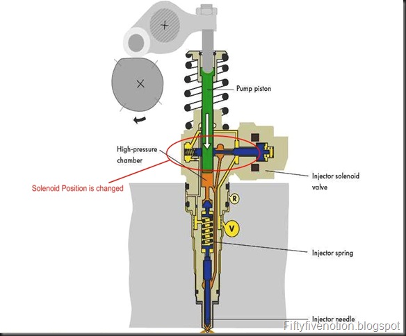
The  main injection cycle is similar to that off Pre-Injection the injector seat is lifted off the seat and thus the fuel is sprayed and this time the solenoid is stayed open for a longer time so that more amount of fuel can be sprayed into the combustion chamber. The pressure keeps raising in the high pressure chamber and the solenoid is made to stay for a longer time so that it can inject more amount of fuel through injector nozzle.

 Main Inection

The position of the solenoid is changed and its made to open for a longer time

Now,When the Solenoid is no longer actuated by the Engine control unit the main injection comes to an end and some of the fuel is sent back to the fuel return lines. Thus the main injection is completed.

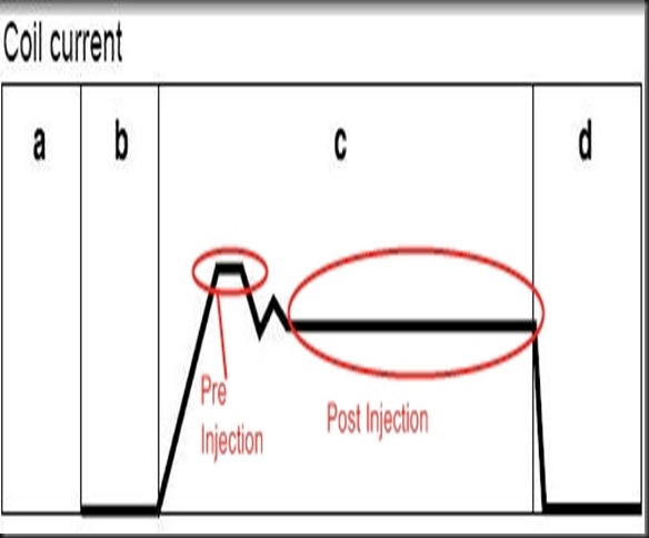
 coil

Coil Current During the various time of Injection

In the above picture we can understand that the coil current is higher when there is a initiation of the Pre-Injection and in the same time a constant current is given during the Post injection time to keep it open for a longer duration.
Sunday, July 10, 2011

Variable Gemomentry Intake System or Variable Length Intake


Intake Manifold:

                               An intake manifold is a system which connects the engine to the air filter and in modern gasoline engines (Fuel Injection) intake manifold is the position where the fuel injector and rails are mounted.
                                                                                                                                                                                

Part’s coupled with Intake manifold:

                                The following are the parts that are normally found in the intake manifold (Fuel Injected),
                               
·         Throttle body a.k.a Throttle Butterfly attached to one throttle cable
·         Fuel Rail
·         Injectors
·         Throttle position sensor  
·          One Vacuum line which connects to the MAP sensor


A conventional Four cylinder inlet manifold


  Intake Manifold Working:

                                            This is mainly designed to get maximum cylinder flow irrespective of the engine RPM. With Respect to the Cross Sectional Area of the Intake Manifold at lower rpm engine requires longer and narrow manifold and at higher rpm the engine requires a shorter length manifold to pull-in the maximum amount of air at least available time.
                                              
                                             To get maximum volumetric efficiency the inlet manifold's are mainly designed. To achieve this it’s all about getting the positive pulse at the right amount (When the inlet valve opens) so that it creates the effect of supercharging in the engine. Imagine that the pressure wave’s keeps travelling inside the inlet manifold and during the suction stroke and the air flows at higher velocities inside the engine.Suddenly the valve closes it creates some pulse which travels in the manifold and the whole theory of this manifold is to make use this pulse to push in as much as air it can when the valve opens again.
                                              
                                                These waves which travel in the manifold hit the plenum and bounce back and if you open the inlet valve at an exact moment when the pulse regenerates and this create a supercharging effect in the manifold thereby pushing few amount of extra air inside the engine.

                                               For street cars the engineers always prefer a longer inlet manifold to get that extra bit of torque and for race lovers like me we always tune it through out our power band to get the maximum power through out the rpm.


FEA Model of a four cylinder conventional manifold


Variable Geometry Intake Manifold - Need:

                                               As we discussed it’s all about receiving that one positive pulse which aid in better volumetric efficiency that helps in better drivability in various rpm’s.


                                               Imagine if the pulse wants to travel for a longer period of time and if the manifold length is shorter the wave will be travelling to and fro in the manifold which results positive pulse produced in the wrong period of time results in wasting the supercharging effect which will be produced, thus the volumetric efficiency is reduced. The situation can go on the opposite side also. Thus the engineers made a compromise in designing the inlet manifold while designing them for street cars. The length of the manifold also depends on the engine configuration also.


                                               Soon after engineers found of sending some extra amount of air by secondary port opening in the manifold by altering the passage. The below is the example of those system. These ports will open in some specific conditions depending upon the vacuum present in the manifold.


As you can see there is a by pass valve which opens and closes depening upon the engine speed


                                               Later they switched to two varying length one shorter and one longer manifolds which were not electronically controlled again a simpler butterfly was used to operate these systems. As technology improved the manufacturers used electronically controlled engine management systems to control these manifold switching with respect to the engine rpm. Few manufacturers also had electro pneumatic valves which controls the throttle butterfly opening and there by shifting the manifold length.


Volvo's method of secondary butterfly opening with the help of  a diaphragm


                                              For some manufacturers motogp and F1 has always been their proving ground and this resulted in lots of improvement in street cars also. VGIS is comparatively cheaper than adopting VVT (Variable Valve Timing) which again improves the volumetric efficiency of the engine, there by manufacturers are also able to cut cost on their products. Yamaha had it own style of doing it. They attached a stepper motor which controls the linear moment of the manifold. The stepper motor receives the signal from the electronic moment through which the manifold is length varies. The engine can either choose a 65mm shorter manifold or a 140mm longer manifold. As cited earlier longer manifold can be used in the lower and mid range rpm and shorter ones are always used in higher rpm.


Yamaha's Variable length Manifold attached to a stepper motor which receives signal from the ECU for chossing manifold length i.e, shorter or longer

The following videos explain the working of the variable length manifold:


Thursday, June 23, 2011

Variable Valve Timing Explained


MIVEC

MIVEC Stand’s for Mitsubishi Innovative Valve timing Electronic Control system and as it says it’s owned by Mitsubishi. It’s similar to that of Honda’s VTEC which was normally used to vary the Inlet valve timing and lift depending upon the engine load.


Why it’s needed?

            By adopting technologies like this manufacturers are able to attain more power, better efficiency and most importantly they were also able prepare themselves for the emission requirements. Sometimes they also help in the branding strategies of the companies.


How does it work?

            It alters the cam profile depending upon the drivers demand. There are two different kinds of cam lobe in each cylinder one called low lift lobe and other is called as medium lift lobe and there is one more lobe called high lift mode which is centrally located between the both. They are connected to one special kind of T-shaped lever which actuates the high lift profile when needed. They get connected to one special piston which works on hydraulic pressure difference.

            During low revs the T- shaped lever (Contains a piston) revolves without connecting them to the other cam lobes. At this time only, the low lift and the medium lift lobes work continuously. When the engine reaches a pre-determined rpm due to hydraulic pressure difference the piston moves up and gets engaged to the high lift cam and thus the high lift cam is engaged to the system. The switching over rpm is said to be around 3500rpm in all MIVEC engines.

            Due to MIVEC smaller valve overlap @ low engine rpm’s result in reducing the amount of fresh charge sent back to the manifold due to long overlap etc.


Structure of MIVEC system        


When MIVEC is disengaged @ Low rev’s the system is like below,       

Take a closer look in the piston position


When MIVEC kicks in after 3500RPM the piston position changes like below,


Take a closer look  of the piston position

Advantages:

      Better power out of a smaller displacement engine.
      More efficiency.
      Emission requirements are attained easily.


Different manufacturers have different name for it few of them are listed below,


BMW
Vanos
Honda
VTEC(Variable Valve Timing and Lift Electronic Control),I-VTEC(Intelligent Variable Valve Timing and Lift Electronic Control)
Hyundai
CVVT - Continuous Variable Valve Timing
Ford
VCT-Variable Cam Timing, TiVCT-Twin Independent Variable Cam Timing
Toyota
VVT- Variable Valve Timing, VVT-I Varies both inlet and exhaust cam shaft independently


You can also refer this video from Youtube for better comparison of the systems,